
PAGE CONTENTS
Objectives
The key goal and driver is to move away from classical converters and master/local references to allow a more generic approach to be facilitated across the spectrum of requirements, whilst concentrating on the overall price, mass and footprint. Using our generic telecoms processing architecture, applicable to a wide range of missions, an end-end RF system is envisaged which can be built using a small set of common building block modules. The three types of equipment developed to EQM are a set of RF equipment suitable for frequency translation (up conversion (U/C) and down conversion (D/C))
-
C / X / Ku band FSS Downconverter Equipment
-
C / X / Ku band FSS Upconverter Equipment
Realised as Master unit and Auxiliary Unit
A set of MRO (Master Reference Oscillator)/ DSP Clock equipments to support not just the converters, but also the digital processor
-
MRO/DSP Clock Equipment
Challenges
The converters need to translate the wanted carriers from the uplink frequency to the DSP interface frequency then back to the downlink frequency range. Realising a single converter design to cover C, X & Ku(FSS) with relatively minor component changes. Achieving up to 500MHz bandwidth with low noise power acceptable alias signals and minimal SWAP.
There are two variants of the DSP Clock Oscillator; 300MHz to 640MHz and 1300MHz to1500MHz.These will differ only in the VCO type and the precise PLL divider and loop filter settings. Achieving the necessary performance for clock jitter and phase noise are key challenges
System Architecture
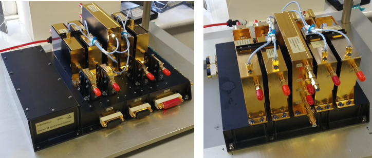
The frequency conversion equipment itself consists of up to 4 chains of RF conversion, down conversion or up conversion, along with the local oscillator generation for each chain, along with dual redundant power solution. These equipments attach to a multi-function active master baseplate providing power and optional digital TM/TC. The Master Equipment can supply up to 20 RF Modules (eg. 16 converters & 4 LO modules), with the modules distributed across 4 equipments. A smaller Auxiliary unit, without fitted DCDC converter power supplies allows the addition of several 4-pack converters per auxiliary unit.
The reasons for choosing 4 converter modules on the equipment are as follows:
-
Shared resources reduces LO & DCDC converter hardware, thereby reducing cost & mass
-
Up to 4 RF Chains share 2 LO Circuits and 2 DCDC Converters
-
Standard heritage DCDC converter can supply power to up to 4 chains plus LO circuit without modification
-
– 4 Converter Chains is a good choice for test system throughput
-
Having 4 chains per unit, configured as single converters/module makes rework and replacement of single chains straightforward
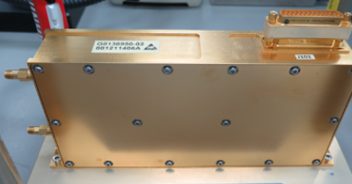
The MRO/Clock is a single box containing OCXO, VCO, PLL, Gain blocks and DC-DC Converter.
Plan
There are 2 phases Pre-Equipment’s Developments; Phase 1
-
EBB1 – Ku-UHF – RF Chain to prove the critical hybrids and filters
-
EM1 – UHF/Ku – RF Chain to prove the critical hybrids and filters*
-
EM2 – MRO – single processor clock (DSP Clock 2)
EQM Phase 2
-
EQM1 – Ku-UHF Converter equipment*
-
EQM2 – UHF-Ku Converter Equipment*
-
EQM3 – MRO – 100MHz & DSP Clock 1
The 3 EQMs will be subjected to an EQM test campaign including EMC, ESD, T-VAC and Vibration/Shock.
The plan was to undertake this development in 20 months.
Current Status
COMPLETED
Airbus has successfully completed the development of all the Equipments proposed. Many of the technological advances realised in the frequency converter development are now incorporated into qualified flight Equipment’s sold to customers.
The MRO/DSP Clock Equipment is now a standard product on many payloads in orbit.