-
StatusCompleted
-
Status date2012-10-03
The main objective of the activity was to study and demonstrate new architectures for low-cost mobile terminal antennas suitable for linearly polarized satellite links. Two scenarios were identified, one for a transmit-only (Tx), and another for a receive-only (Rx) antenna. The Tx scenario is the classic beam-switching scenario, where the field of view of the antenna is divided into a number of sectors, and the antenna generates a beam to cover each of these sectors. The objective was to find ways to reuse the aperture for all beams of the switched-beam set, without requiring a separate beam-forming network for each beam.
A switched beam approach was attempted for the RX antenna, but due to its size (and the number of beams to switch between) it was found impossible to implement. An alternative approach was decided, again attempting to avoid any costly proprietary MMIC design, this time by using 1 bit phase shifters with off-the-shelf diodes.
The crude quantization of the phase controls results in high sidelobes and polarization errors if naively implemented.
The objective was to demonstrate ways to control these drawbacks.
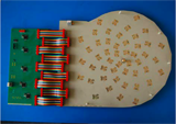
Figure 1 – TX and RX antenna EBBs
The main challenges addressed in this activity are the following:
- Low cost
Both the antennas innovative concepts were drawn having in mind a reduction in cost, when compared to classical approaches. This was achieved thanks to a reduced number of switches and beamforming layers in the TX antenna and a one bit cell, aperiodic spacing and rotation of the elements in the RX one. - No phase shifters
Both the antennas were designed to work without any special MMIC covering the required FoV. In the RX case the antenna was also able to turn the linear polarization to adjust for a usage in different world locations.
This activity has allowed to develop and validate an innovative antenna architecture for satellite communications on the move.
The developed antennas have several major advantages and in particular:
- A small thickness (less than 7 cm) allowing the installation in fast moving vehicles with minimum drag, noise and visual impact,
- High reliability thanks to the electronic steering that reduces the mechanical movements,
- Low-cost allowing the application of the products to consumer market,
- High radiation efficiency maximising the G/T of the antenna and hence minimising the required size,
- Dual linear polarisation with electronic agility to to cope with polarisation rotation due to geographical displacements and vehicle movements,
- Large bandwidth covering the complete Ku receive band from 10.7 to 12.75 GHz.
Thanks to these attributes, the HiSat antennas have a competitive edge with respect to other existing commercial solutions. The combined form factor, reliability and cost will allow to increase the application of Ku-band satellite communications systems in several market segments.
Regarding the TX antenna, the frequency range is the Tx transmit Ku-band (14.0 to 14.5 GHz) and the antenna is operated in single linear (vertical) polarization. The adopted beam plan consists of twelve shaped sector beams with a directivity of 11 dB, each of them covering the full elevation range (20° to 60°) and a sector of 30° in azimuth, as suggested in Figure 4(a). Only one beam is used at a time.
Figure 2 Beam plan for Tx antenna, and structure of the shared beamforming network (arrows at element positions)
The goal is to use the same physical aperture to produce the twelve beams. This is achieved by forming each beam with a parallel-series feeding network, overlapping three beam forming networks in three different directions, and applying two levels of reuse:
- Each series feeding network is used for both the backwards and the forwards direction when fed from either end.
- The elements are placed on the nodes of a trihexagonal lattice so there are three elements on the space that is typically used for only one. To successfully implement this architecture, two challenges had to be overcome: the design of the excitations and the implementation of the beamforming network in a small number of layers.
Figure 3 :Constrained excitation and copolar directivity of the two synthesized beams for the Tx antenna
Regarding the RX antenna, the use of 1-bit phase-only controls on a phased array results in a number of issues. The most important ones are the appearance of quantization lobes and the increase of the polarization control error.
These quantization lobes can be spread out by placing the elements in an aperiodic arrangement and by applying an appropriate rotation to the carefully designed elements. One the best features of the aperiodic arrays is that the sidelobe floor and the polarization errors due to quantization both decrease as the number of elements increase, which is not the case for regular arrays. This, together with a particular rotation of the specially designed control element cells where in details investigated in the study, resulting into the innovative configuration shown below.
Figure 4 :View of the RX EBB with aperiodic placement and element rotation
Figure 5 :Arrangement of the element in the demonstrator and measured performances
The activity has been executed in two main phases:
Review of requirements and specifications and Baseline Design Requirements have been reviewed with the customer and final specifications have been set accordingly. At this point the design was split between TX and RX antennas. The initial architectures have been studied and traded-off in a Baseline Design. Critical Breadboard have been manufactured to limit the risks.
Antenna EBBs Design , Manufacturing and Measurement
Design and development of the Tx and RX antenna EBBs. Both boards have been tested in the anechoic chamber according to the test plan approved by ESA. The results were used for drawing conclusions.
The project has been successfully completed. The prototypes of the TX and of the RX antennas have been manufactured and tested. Both TX and RX antennas results demonstrated the capabilities of the studied concepts.


