
PAGE CONTENTS
Objectives
Satellite manufacturers are requesting light, compact and broadband equipment. Broadband equipment increases satellite manufacturers flexibility to satisfy the increasingly demanding requirements and the possibility to reuse equipment in different missions. Cost reduction is always pursued. In order to evolve with our Customer needs, a new concept must be used. The development of a new antenna line offering a good trade-off between mass reduction and broadband increase is necessary. To achieve this goal, the use of light, easy-to-manufacture antennas based on spline profile horns has been identified. A design of a compact and easy to manufacture broadband OrthoMode Transducer (OMT) polarizer is required to have a completely competitive product.
Challenges
The main challenges are summarized in the table below, showing what our customers require:
| Customer | Customer Problems/Needs |
| Space Systems Loral (US) |
|
| Airbus Defence and Space (FR) |
|
| Orbital ATK (US) |
|
| MDA (CAN) |
|
| Thales Alenia Space (FR) |
|
Most of our customers have showed interest in the promising characteristic of the Global Horns based on spline profiles integrated with a compact and broadband OMT.
System Architecture
The figure below is a functional block diagram of the product that identifies its main functional modules and external interfaces.
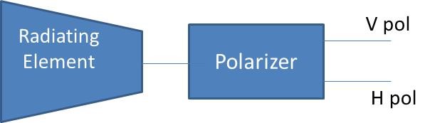
The main functional modules of the Ku-Band Tx-Rx Global Horn are described in the table below.
| Module | Functions/Features | Description | Critical Technologies |
| Radiating Element Set |
Radiating element Matching section |
RF radiating element with global earth coverage | Smooth profile horn |
| Polarizer Set | Polarizer | Dual linear polarizer | OMT based on a two-fold symmetric junction |
The external interfaces of the product are summarised in the table below.
| Interface Identification | Key Parameters | Purpose |
| RF Interface: V pol |
Vertical polarization sense Return loss |
Standard RF Interface WR75 |
| RF Interface: H pol |
Horizontal polarization sense Return loss |
Standard RF Interface WR75 |
| Thermo-Mechanical Interface | According to General Design Interface Requirement | Thermo-Mechanical Interface to the satellite |
Plan
Two phases, one for design and one for qualification, are foreseen.
Antenna (Horn & OMT) Design phase:
The design phase shall include the following tasks:
- Software development for the simulation and optimization of horns based on spline profiles.
- Full simulation of electrical performances.
- Issue of the corresponding electrical analysis.
- Modelling of the antenna.
- Mechanical analysis.
- Thermal analysis.
- Issue of the manufacturing drawings and all the PDR and CDR documents
The antenna design and analysis shall be documented. The design shall be approved as well as the corresponding manufacturing drawings in the CDR/MRR. The manufacturing of the EQM shall be authorized in the corresponding CDR/MRR meeting.
Antenna (Horn & OMT) Qualification phase:
It includes the EQM production and testing. A comparison between the obtained results and the predicted ones shall be performed.
A PIM test in temperature within a radiation transparent chamber is included.
A TRR and a Final Review milestones are expected for the Qualification Phase.
Current Status
Completed
Companies
