-
StatusCompleted
-
Status date2017-01-30
-
Activity Code4E.020
This activity has been performed to study and to demonstrate the potential of Magneto Rheological fluids in order to provide tuneable speed regulator solutions. The development has covered the design, manufacture, and test of an Engineering Model of a self-standing speed regulator unit, based on Magneto Rheological fluid technology, suitable for the control and the regulation of the deployment speed of future Telecom platform appendages. Testing of the Engineering Model has included lifecycle, full vibration, shock, and thermal vacuum cycling.
Main Technical Requirements
The following requirements have been verified by performance and function tests:
The Speed Regulator shall be able to dissipate 2.0 J w/o exceeding the damper allowable loading within the first 5 degrees of travel.
The Speed Regulator shall perform without failure at deployment speed between 0.01 and 0.5 rad/s.
Same rate in CW and CCW direction within 5% under the same environmental conditions.
Main characteristics – MARF shall be stable (within 10%) throughout the test campaign.
Maximum friction in the system shall be 1 Nm.
MARF shall not use more than 5W of electrical power.
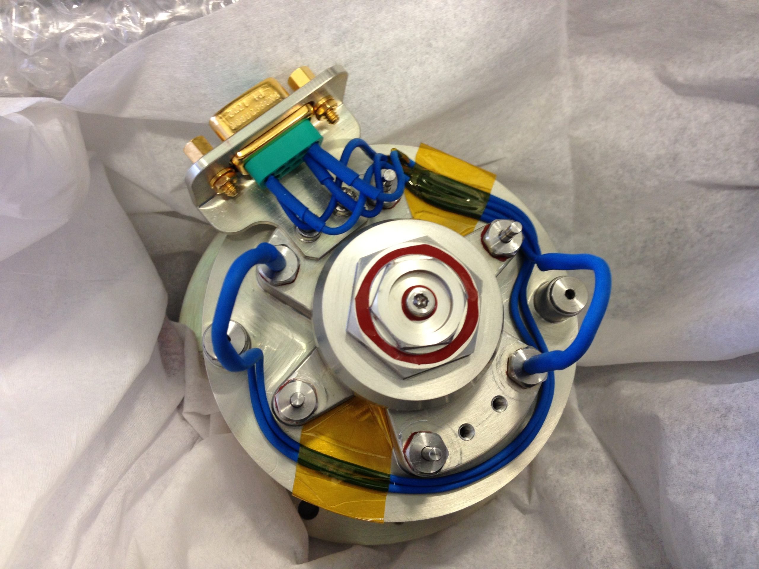
Identification of the optimum magneto-rheological fluid - maximum performance, low settling effects, compatibility with specified environment;
Fine tuning of gap size/disc spacing for optimizing rheological performance;
Optimization of internal seals, avoid leakage effects, keep mechanical resistive torque low;
Filling with oil, define adequate procedure to prevent internal voids;
Keep complexity and mass as low as possible.
The product facilitates an adjustable speed of deployment for a wide range of appendages. Its design features a low level of complexity, as the speed regulator is essentially a passive device. Only very limited electrical power is needed for controlling the deployment. The deployment speed may even be regulated over the travel range, i.e. soft latching may be realized by the application of this device.
The main performances of the MARF have been demonstrated; these are summarized here below:
- Provision of a resistive torque of up to 10 Nm; the torque is ad-justable by applying a drive current in the range of +1A and -1.4 A.
- The minimum resistive torque amounts to approx. 1.5 Nm; this is due to mechanical friction in the system.
- The resistive torque can be applied for a speed range of 0.01 to 0.5 rad/s.
- The mechanism provides the resistive torque in both CW and CCW directions.
- The dissipative capability of the mechanism amounts to 2 J (for a travel of 5 deg.)
- The number of operations is unlimited (theoretically); the number of lifecycles demonstrated by test amounts to 4060.
- The power consumption amounts to less than 5 W, typically, for a drive current of 1 A.
- The resistive torque is almost independent of the speed; it is mainly a function of the drive current.
The MARF is compatible with the following environmental conditions:
- Temperature range: -55 ..+100 degC (operational)
- Shock: 2000 g SRS (3 kHz to 10 kHz)
- Vibration: 16.9 g rms (random); 50 g sine up to 60 Hz; 15 g sine from 60 Hz to 100 Hz
- Lateral mechanical load: 220 N (at 12 mm distance from external I/F)
SYSTEM ARCHITECTURE
Magnetic particles sized 0.1–10 µm are suspended in a carrier fluid, w/o magnetic field randomly distributed.
Figure: Magneto Rheological Fluid Functional Principle
With magnetic field applied the particles align themselves along the lines of magnetic flux. This results in higher shear strength of the fluid.
CAD Model: Disc Fixation
The torque generated results mainly from the magnetic field. The working principle of MARF is based on the use of MRF in gaps between rotor discs and stator discs. When a magnetic field is applied to the fluid the behaviour of the fluid will change. The magnetic particles inside the fluid have the ambition to build a structure like a chain which results in a higher shear strength of the fluid. The resistive torque is proportional to the shear stress of the fluid and can therefore be controlled by the magnetic field via the current in the coil.
CAD Model: RUAG Space Austria
Figure: MARF Functional Principle
Some technical improvements of the realized concept need to be carried out, like mass optimization, reduction of the gap size and of the total mass. Furthermore, for transferring the development into a commercial exploitation phase, the following activities will be needed:
- Tailoring the product towards specific customer requirements
- Formal qualification of materials, processes and of the unit
The development was started early 2011 and completed mid 2015. Its main objective was to design, analyse, manufacture, and test an Engineering Model of a Magneto Rheological Fluid Speed Regulator for space applications. A Technology Readiness Level (TRL) of 4 was achieved, i.e. proof of concept and engineering model validation.