-
StatusCompleted
-
Status date2019-11-27
-
Activity CodeFB9.32
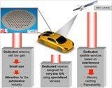
The objective of the NATALIA project was to realise a Ku-band antenna front-end which will be part of a mobile satellite terminal for automotive applications. The complete demonstrator will consists not only of the antenna front-end envisaged here, but also of a receiver front-end which is being developed in a separate project.
The NATALIA antenna is fully electronically steerable, receive-only, and is suited for customised KU-band broadcast services of providers like SES Astra. The design and construction of an antenna front-end providing mobile services to vehicles, presents several challenges.
A very important aspect is, that for fixed Ku-band services, relatively large (60-90cm diameter), highly directive antennas are used, commonly parabolic dishes. This is of course not possible for products like the NATALIA antenna that are intended for integration into or onto vehicles, hence size is a critical factor.
Antennas with sizes of around 20 cm in diameter and a height of a couple of cm’s are considered realistic for mass-market deployment for automotive applications.
The linear polarisation was a major design challenge because it requires, besides beam steering logic, also polarisation pointing logic. This increases the complexity of the system by more than a factor of 2.
For the moment, it is anticipated that the NATALIA antenna will be sold as an after-market product because this allows for a more flexible and rather simple installation. This implies however that the antenna must be very slim in order to be aesthetically appealing which is another major design challenge. And last but not least, the buildup of the antenna should be extremely cost-effective in order to successfully address the mass market.
The current NATALIA design is based on a classical phased array approach using RF phase shifter devices. The design of LNA and phase shifter in MMIC-technology with adequate performance and as cost-effective as possible, was one of the major building blocks within the project.
The other key issue was the multilayer buildup. The integration of antenna elements, MMIC components, feeding network, and digital components in one multilayer structure was without doubt the true challenge of this project.
The NATALIA antenna together with the receiver front-end will constitute a new generation of mobile satellite terminals: slim antenna front-end, intelligent receiver and smart broadcast services for the mass market. Satellite reception in cars would be possible without disturbing its aesthetics. This would not only open new markets for service providers but also for other non-automotive applications.
The main specifications to be satisfied for the NATALIA-front-end are the following:
- Operating frequency: 10.7 GHz – 12.75 GHz
- Operation mode: Rx-only
- Polarisation: linear
- G/T: > -6 dB/K
- Aperture size: 20 cm in diameter (EU), 30 cm (USA)
- Estimated manufacturing price: < 1,000 Euro
- Scan range: 20°- 60°in elevation from horizon, 0°- 360° in azimuth.
The latter values have been established after elaborate discussions with the car industry and service providers.
The NATALIA project is divided into two phases.
- The first phase considers a survey of possible antenna architectures and concepts resulting into a global definition of the antenna concept. This phase has been concluded and a baseline design has been defined. This serves as the input for the second phase.
- The second phase focuses on the technical implementation of the baseline design concept and the realisation of a demonstrator. The second phase finished in April 2012.
Phase 2 has been concluded successfully, the antenna performance as expected and the calibration method proofs to be very effective. The antenna has been measured in the anechoic chamber of IMST in far and near field. The antenna under test is shown in the next picture.
NATALIA-Antenna under test
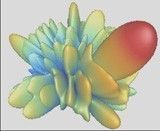
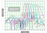
The antenna has been measured in far and near field and shows an excellent behaviour, the performance is almost as expected. In the next graphs, some of the measurement results are shown.
Far field pattern
Far fields for scanning in a plane


