
PAGE CONTENTS
Objectives
© Airbus Defence and Space NL
The first phase of the development covered requirements definition, technology investigation, bread-board testing and concept design. A trade-off was made between the concepts designs, and decisions were made on the concept used for the Engineering Model.
Key elements in the design were to increase the pre-load capability, lower the shock induced with the actual release, and ensure a wider operating temperature range. At the same time increase the flexible positioning tolerances and keep a compact and structure that is able to cope with the high mechanical loads.
For the design we have chosen to use a Thermal Knife cutting technology in combination with a VECTRAN cable for the release of the system. The VECTRAN cable offers a high preload capability of 15kN typical load and above 50kN break load.
This model was subjected to a series of tests. The result of the tests were reviewed with ESA
Benefits
The NELS product offers the following key benefits:
- Ultra-low release shock
- Extended thermal envelope
- Higher pre-tension than ARA mk3 HDRS, up to 15kN
- Able to release after a time to reach GTO
- Competitive pricing
- High reliability (leveraged from extensive ADSN experience on hold down and release systems)
Features
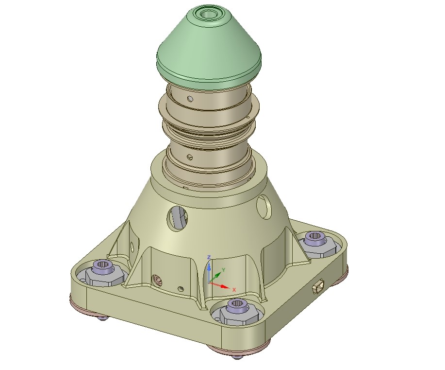
The NELS mechanism is functionally very simple at the top level. It is designed to provide a structural interface to deployable structures with the spacecraft during launch operations and to release them when in orbit.
Two main drivers for the structure become clear with respect to the physical architecture of the NELS mechanism. That is the main structure with an interface to the spacecraft, and that is the cable structure.
The cable structure comprises of the cable, the end fittings on the top and the bottom of the cable and closing the load patch through a dedicated section of the structure. Internal to the structure the Vectran cable is exposed to 2 (main and redundant) thermal knives that each can cut through the cable in an angular motion when the knives are heated up.
The load path of the cable structure interfaces with the part of the structure that interfaces with the S/C structure.
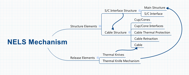
Above are the key components depicted of the NELS: the structural elements, and the release elements.
The structural elements were tested to demonstrate it could withstand the applied loads while maintaining the required pre-tension through the cable and the structure.
The properties of the cable cutting and the properties of the thermal knives were subject of the tests.
Further features include:
- A redundant release switch
- Features that allow to easily replace be cable
- connection to the S/C systems via redundant Sub-D connectors
- White cap for thermal protection
Challenges
Main challenges have been to find the material for the cable and[A1] come up with a design for the cutting mechanism that is compatible with that cable and fits in a design that meets the project requirements. In particular finding the material for the cable and how that can be cut in a controlled manner has been the key objective during the development. After that making a design for the Hold Down that can handle the higher loads.
System Architecture
Increased demands from the S/C applications, including satisfying higher margins of safety requires a re-design of the existing ARA mk3 design. The need for higher pre-tension systems from S/C conditions (in certain failure modes) and requiring a larger temperature range than can be met with the ARA mk3 design.
Therefore the NELS development has the approach to extend the pre-tension to 15kN with a design that that has a high level of similarity with the existing ARA mk3 design, and to increase the temperature envelope.
Plan
In summary the project covered the following steps:
- Requirements consolidation
- Complete the conceptual design
- Preliminary design of the EM model and the related tooling and test set-up.
- BB and subsequently EM testing of the Thermal Knives.
- Develop an Alternative for the Thermal Knives
- Restraint cable development testing
- Restraint cable EM testing
- Build the EM NELS, tooling and test set-up
- EM Functional testing
- System characterisation, including pre-load testing, humidity test, random vibration, APTC and repetitive cutting tests
- Test reporting
Current Status
All activities in the ARTES 5.2 project are completed, with the exception of testing a 2nd run of the Thermal Knives and its assembly; ready to progress to formal qualification under a ARTES 3-4 project .