-
StatusCompleted
-
Status date2014-02-17
-
Activity Code5A.016
The objective of this activity was to define end-to-end on-board self-calibration techniques for payloads using advanced distributed elements as active/semi-active antennas and Multi Port Amplifiers, to identify architectural options for their implementation, to perform a trade-off between those options and to analyse their feasibility and performance. The calibration shall be performed avoiding telecommunication service interruption and minimizing the degradation in the Quality of Service.
The study has enlighten the trade-off between the need for avoiding service interruption and guaranteeing minimum degradation in Quality of Service (in terms of BER) as well as limiting TWTAs IBO variation and the need to achieve good amplitude & phase residual impairments between payload RF chains in order to meet the stringent requirements in terms of minimum antenna gain and beam isolation of next generation satellite missions.
The extensive analyses, simulations and measurements allowed to identify suitable calibration techniques and architectures meeting all the requirements with minimum complexity.
Use of a calibration system should result in following benefits:
Main advantages of an On-board Calibration include performance enhancement of any RF chain in any redundant configuration, for any operational point of the Payload whatever the operational traffic and in any temperature/ageing condition.
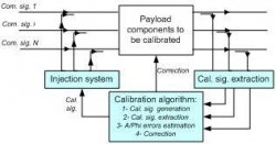
The basic idea of the proposed concept for the on-board calibration sub-system addressed in the study relies on a closed loop calibration consisting of four steps:
- On-board calibration signal generation and injection into payload RF chains (after Digital Transparent Processor – in TX). The calibration signal is injected in the communication signals guard bands (in case of CW, chirp or spread spectrum signals) or may be partially overlapped with communication signals (in case of spread spectrum and chirp signals),
- Extraction of the calibration signal (before the TX Beam-Forming Network in case of RF chain frequency equalisation and before radiating elements for TX Antenna calibration),
- Estimation of amplitude and phase impairments between payload RF chains,
- Application of amplitude and phase corrections through a digital filter in the DTP (for equalisation of RF chain frequency responses) and through the Beam-Forming Network (for antenna calibration). The main difference between RF chain frequency equalisation and antenna calibration consists in the fact that amplitude and phase impairments of RF chains are evaluated only at centre frequency of beam under calibration, while they are evaluated at several frequencies for RF chain frequency equalisation. This means that the calibration signal needs to be injected iteratively at different frequencies for RF chain frequency equalisation.

Project Plan has been composed of five major tasks:
- Payload front-end architectures and calibration requirements definition
- Review and Trade-off of state-of-the-art calibration techniques
- Calibration system definition and performance analysis
- Technology Roadmap definition and proof-of-concept definition
- Measurement of amplitude and phase estimation performances over a Digital BFN breadboard (CCN)
The Project is COMPLETED.
- {Spread Spectrum +FFT algo}: best compatibility of amplitude and phase estimated impairments with expected values measured by an high accuracy oscilloscope;
- {Chirp + FFT algo}, {Chirp +Correlation algo} and {Spread Spectrum +Correlation algo}: best compatibility of amplitude and phase estimated accuracy with the 0.05dB/1.12° rms accuracy requirement.
Axes of further improvements have also been highlighted, mainly consisting in the need for developing calibration subsystem proof of concepts/engineering breadboards fully representative of the operational behaviour of the target calibration subsystem in closed loop (i.e., addressing both impairments estimation and correction) and under traffic conditions.


