PAGE CONTENTS
Objectives
The main objective of this ARTES project is to develop a prototype of a high performing Q/V Band Direct Quadrature Demodulator RFIC, improving the solution footprint and power consumption compared to standard heterodyne down conversion approach.
The following main characteristics reflects the Direct Quadrature Demodulator:
- Achievable RF frequency – 47.2 to 52.4 GHz.
- Achievable demodulation (channel) bandwidth – ≥ 2 GHz.
- Conversion gain – ≥ 15 dB.
- Impairments (e.g. I&Q unbalance) < 2°.
- Receiver minimum Power Detection Level – ≥ 35 dB.
- Power consumption ≤ 1 W.
- High integration to reduce size.
Challenges
The main challenges with the direct-down conversion architecture are the sensitivity to LO leakage to the RF input, causing DC-offset in the I/Q-baseband amplifier chain. Even-order distortion causing large-signal interferers at RF to be down converted to baseband, and the high gain needed in the RF and baseband paths as no amplification can be applied at an IF frequency.
System Architecture
The top-level block diagram of this Direct Quadrature Demodulator RFIC is outlined below:
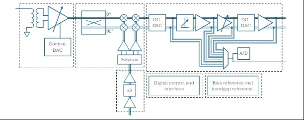
The main blocks are RF balun and VGA, followed by a Mixer, and then a baseband circuitry handling amplitude control, amplification and DC-offset compensation.
Plan
The project is organised in the following phases:
- Study and technical specification completion.
- Design phase.
- Hardware fabrication.
- Performance validation.
- Project and results summary.
- Project closure.
Current Status
The project is in design phase and will perform a (PDR) Preliminary Design Review for the schematics outline and some early simulation results.